Section 7.1 STL file Creation in CalcPlot3D
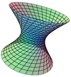
One of the CalcPlot3D's newest features is its ability to save a surface to an STL file. This STL file can then be used to print a solid 3D surface model using a 3D printer, sometimes called a rapid prototyping machine. For example, here are the saddle, \(z = x^2 – y^2\text{,}\) and the parametric surface I call the Big Knot.


In order for the STL file to work well with the 3D printer, the surface must be given sufficient thickness. To address this issue, CalcPlot3D will automatically give the thickness you specify to a surface before creating the STL file. The app must create a closed solid to represent the surface if you wish it to print on a 3D printer.
To give this feature a try, first find a surface that you would like to print to a 3D printer and graph it with CalcPlot3D.
Open CalcPlot3D.
-
From the File menu select Create an STL file from the plot. A dialog will appear like the one below.

Figure 7.1.3. STL dialog in CalcPlot3D Enter the name you wish to give to the solid, and then enter the approximate size you expect to print it at and the desired thickness. These will be used together with the dimensions of the 3D plot window to determine the approximate correct thickness to use with the surface to account for the scaling to be done in the printer application. You may need to experiment a little with these values and your 3D printer software to get the thickness just right.
If the surface you wish to print is already a closed 3D surface like a sphere or a torus, you can specify that no thickness be given to the surface before printing, or you can still use a thickness, depending on how you desire the printer to fill the void inside the closed surface. In this case, if you choose to give the closed surface a thickness, you will need to choose between using the Opposite Normals direction (generally inside the closed solid), the Normal Direction (generally outside the closed surface), or the Half-and-Half option, which goes both directions half the thickness and creates two new shells with the same basic shape.
The Half-and-Half option is always best for surfaces that flip orientation in the middle of a surface like a Möbius Strip or a Klein Bottle.
Use the View Solid button to see what the surface/solid will look like before saving the STL file. Note that this can take a little while, during which the cursor will remain a hand. The more faces you have in the plot (for a more accurate printed solid), the longer this processing will take.
For regular surfaces given by functions of two variables like the saddle above, I prefer the \(z\)-shift down option since it preserves the exact shape of the surface on the bottom as well as the top of the printed surface. But you need to compensate for the fact that the thickness will vary over the surface and be least thick where the surface is steepest in the \(z\)-direction.
Once you see the solid in the plot, you can click on the plot and then type the n-key to view the surface normals of every triangular face in the plot. This can look a little busy, but can be helpful to check, as it is generally preferred (and possibly required) that the normal vectors of all faces point outwards. Sometimes this may require you to adjust the parameterization of a parameterized surface, for example.
Before saving the STL file, note that you can select either a Binary STL file (the default) or an ASCII STL file. The benefit of the Binary STL file is that it is much smaller than the ASCII STL file (about 1/5 the size). The benefit of the ASCII STL file is that you can actually read it to view the normal and vertices of each face.
Once you are ready, click on the Create File button. You should see the file downloading to your default download folder (in Chrome) or may need to choose to download it in some browsers.
Once you have created the file, you will need to check it out in the 3D printer software (slicer) you plan to use. It may also be helpful to download an STL viewer like MeshLab or Blender. These allow you to check the surface for thickness and for other possible problems before you print it. They can also usually be used to fix these problems. See tutorials online.
Now you should be ready to print to the 3D printer using the 3D printer’s software. There is still some room to play with the surface in this software, scaling it appropriately and choosing how you want to fill the surface and how much support material to use. Ask your local expert to help you with this step. By the way, it can take a long time to print one of these surfaces, depending on the solid’s size and the printer and material being used to print it. My 6 in. x 6 in. saddle surface above took 13 hours to print and the 4 in. x 4 in. knot took almost 9 hours. But 3D printers are getting faster and less expensive all the time.
If you’d like to share your favorite 3D print-tested STL files along with an image of the solid/surface, along with any activities you may have developed to accompany them, please send them to me at [email protected].